Mini-Meg 100 Product Features
GENERATOR
• Small Size
• 2 Channels
• 2 Outputs / Channels
• 350 watts/channel
• Phase Shifting
• Programmable Recipes
• Choice of Frequency
• 700 kHz
• 950 kHz
PROCESS TANK
• Tank Material Options
• PVDF
• Stainless Steel
TRANSDUCER
• Ambient to 70°C Liquids
• Multiplexing / Full On
Perfect for R&D Lab Applications & Processes
• Semiconductor
• MEMs
• Disk Drives
• Optics
- Solar
- Particle Removal
- Post CMP Clean
- 2D Graphene Particles
• Wet Etch
• SCI Clean
• Resist Removal
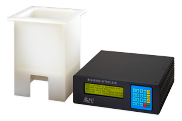
Model 6000 Mini‐Meg Generator
Notice: PCT Series 6000 Megasonic Generator will be discontinued September 30, 2026. A replacement PCT Series 24000 MUX Megasonic Generator that is backwards compatible will be available end of Q3/early Q4.
Mechanical Specifications
| Size | Width 14.0”, Length 14.0”, Height 5.0” |
| Material of Construction | Anodized Aluminum |
| Mounting | Horizontal or Vertical |
Electrical Specifications
| Voltage Rating | 208‐240 VAC, 50/60 Hz |
| Current Rating | Max 10 amps |
| Environmental Operating Range | 0° to 27°C |
| Storage Temperature Range | ‐25° to 50°C |
Megasonic Amplifier Operation Specifications
| Independent Power & Frequency Control for each RF Output | |
| Number of Channels | 2 |
| Number of Outputs per Channel | 2 |
| Maximum RF Output per Channel | 350 watts |
| Programmable Recipes / Channel | 7 |
| Frequency Changes / Recipe | 4 |
| RF Output Power Tolerance | +/‐ 10% |
| Output Designations | Array 1, Array 2 |
| Frequency Bands (Choice of 1) | 700kHz, 950kHz |
| Frequency Resolution | 100 Hz |
| Frequency Accuracy | +/‐ 100 Hz |
| Programmable Sweep Functionality | 1‐10 KHz |
| RF Output Connectors | DB15F |
External Interface
| External Interlock | DB15 Male Connector, +5v Loopback Liquid Level |
| Communication Ports | SECS II: RS232: DB15 Male connector |
| Transducer Connections | 4 each DB15 Female connectors |
| Power Plug | 3 ‐ prong IEC Appliance Connector |
Displays/User Interface
| Power On/Off Switch |
| 4 Line 40 Character LCD with keypad or PDA/LCD Touch Screen Monitoring for Frequency vs. Time, Power vs. Time, and more |
Facilities Requirements
| N2 or CDA supply | 1‐2 psi @ 1/4 scfm |
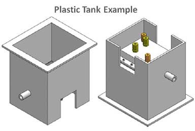
Mini‐Meg 100 Tank
PVDF Tank Mechanical Specifications
| Size: Outside Dimensions Inside Dimensions | Width Length Height 8.75” x 9.50” x 9.55” 6.75” x 7.50” x 5.80” |
| Material of Construction | PVDF Plastic |
| Drain Port | PVDF Drain 1/2″ NPT |
Stainless Steel Tank Mechanical Specifications
| Size: Outside Dimensions Inside Dimensions | Width Length Height 8.75” x 10.58” x 10.51” 6.75” x 7.50” x 5.81” |
| Material of Construction | Electro Polished Stainless Steel PFA Coated Stainless (+$500) |
| Drain Port | SS drain with 1/2” ball valve |
Quartz Tank Mechanical Specifications
| Size: Outside Dimensions Inside Dimensions | Width Length Height 8.75” x 9.75” x 10.25” 5.5” x 6.50” x 5.81” |
| Material of Construction | Quartz with plastic housing |
| Drain Port (Optional) | drain with 1/2” ball valve (+$295) |